Note
This page was generated from tut/1-Overview/1.1-Quick-start.ipynb.
1.1 Quick start
![]()
![]()
💡 Running in Colab or Binder? Skip the desktop GUI install — the cell below grabs the lite (no-Qt) wheel, and
qm.gui(design)auto-picks an inline matplotlib viewer with the same API (gui.rebuild(),gui.screenshot(),gui.edit_component(...)) as the desktopMetalGUI.
[ ]:
# In Colab / Binder, uncomment to install Quantum Metal (lite, no Qt).
# Locally you should already have it via `pip install quantum-metal` or
# `pip install 'quantum-metal[gui]'` for the desktop GUI.
# !pip install -q quantum-metal
Import Qiskit Metal
[2]:
import qiskit_metal as metal
import qiskit_metal as qm  # alias used by qm.gui / qm.view
from qiskit_metal import designs, draw
from qiskit_metal import Dict, open_docs

%metal_heading Welcome to Qiskit Metal!
Welcome to Qiskit Metal!
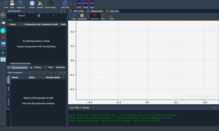
My first Quantum Design (QDesign)
A QDesign is the canvas that holds your chip components. Start with the planar variant:
design = designs.DesignPlanar()
gui = qm.gui(design)
qm.gui(design) is a factory: it returns the desktop MetalGUI when you have PySide6 and a display, and an inline matplotlib viewer (MetalGUIHeadless) otherwise. The same gui.* API works in both.
Run the cells below to instantiate a design and view it. The chip starts empty — let’s add a qubit.
[3]:
design = designs.DesignPlanar()
gui = qm.gui(design)  # Qt locally, inline matplotlib in Colab/Binder
[4]:
gui.screenshot()
[5]:
%metal_heading Hello Quantum World!
Hello Quantum World!
My first QComponent — a transmon qubit
Quantum Metal ships a ready-made transmon in qiskit_metal.qlibrary.qubits.transmon_pocket. Adding one is a single line; the GUI refreshes automatically.
[6]:
# Select a QComponent to create (The QComponent is a python class named `TransmonPocket`)
from qiskit_metal.qlibrary.qubits.transmon_pocket import TransmonPocket

# Create a new qcomponent object with name 'Q1'
q1 = TransmonPocket(design, "Q1")
gui.rebuild()  # rebuild the design and plot
[7]:
# save screenshot
gui.edit_component("Q1")
gui.autoscale()
gui.screenshot()
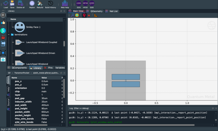
Inspect the component we just created:
[8]:
q1
[8]:
name:    Q1
class:   TransmonPocket
options:
  'pos_x'             : '0.0um',
  'pos_y'             : '0.0um',
  'orientation'       : '0.0',
  'chip'              : 'main',
  'layer'             : '1',
  'connection_pads'   : {
                        },
  'pad_gap'           : '30um',
  'inductor_width'    : '20um',
  'pad_width'         : '455um',
  'pad_height'        : '90um',
  'pocket_width'      : '650um',
  'pocket_height'     : '650um',
  'hfss_wire_bonds'   : False,
  'q3d_wire_bonds'    : False,
  'aedt_q3d_wire_bonds': False,
  'aedt_hfss_wire_bonds': False,
  'hfss_inductance'   : '10nH',
  'hfss_capacitance'  : 0,
  'hfss_resistance'   : 0,
  'hfss_mesh_kw_jj'   : 7e-06,
  'q3d_inductance'    : '10nH',
  'q3d_capacitance'   : 0,
  'q3d_resistance'    : 0,
  'q3d_mesh_kw_jj'    : 7e-06,
  'gds_cell_name'     : 'my_other_junction',
  'aedt_q3d_inductance': 1e-08,
  'aedt_q3d_capacitance': 0,
  'aedt_hfss_inductance': 1e-08,
  'aedt_hfss_capacitance': 0,
module:  qiskit_metal.qlibrary.qubits.transmon_pocket
id:      1
Default options
Every QComponent has a default_options dictionary. Quantum Metal parses these strings into numeric values during rebuild(). You can change them through the GUI or the Python API — both call the same underlying setters.
[9]:
%metal_print How do I edit options? API or GUI
Both paths converge: the GUI just calls the same API you’d write in a notebook.
[11]:
# Change options
q1.options.pos_x = "0.5 mm"
q1.options.pos_y = "0.25 mm"
q1.options.pad_height = "225 um"
q1.options.pad_width = "250 um"
q1.options.pad_gap = "50 um"

# Update the geometry, since we changed the options
gui.rebuild()
[12]:
gui.autoscale()
gui.screenshot()
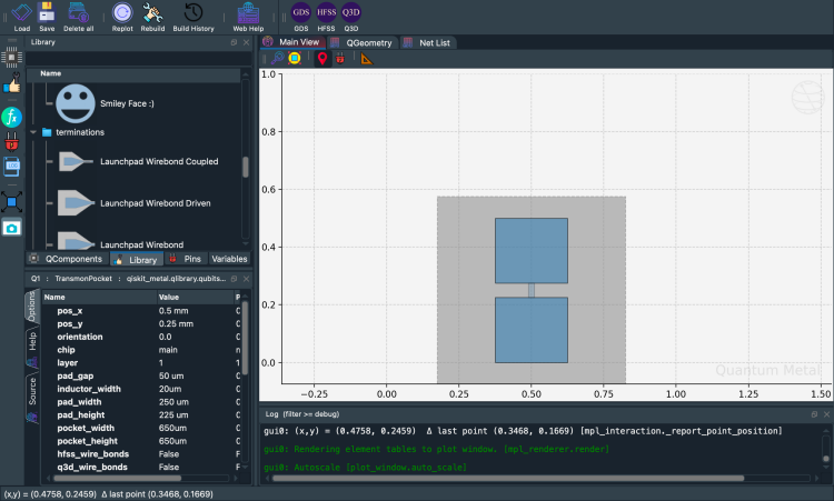
Compare before and after
Design-as-code means every parameter change is immediate and visual. qm.view() renders into any matplotlib axes — drop two of them side-by-side to see what changed.
[ ]:
import qiskit_metal as qm
import matplotlib.pyplot as plt

# Record the original value so we can restore it
_orig_pad_width = q1.options.pad_width

# Make a change
q1.options.pad_width = "550 um"
design.rebuild()

# Side-by-side comparison rendered to a PNG so it displays inline in
# Jupyter regardless of which matplotlib backend the GUI activated
# (the desktop MetalGUI sets `QtAgg`, which doesn't render Figures
# directly into notebook cells; ``display(fig)`` falls back to a
# text repr otherwise).
fig, axes = plt.subplots(1, 2, figsize=(12, 5))
qm.view(
    design,
    components=["Q1"],
    title=f"Original  pad_width={_orig_pad_width}",
    ax=axes[0],
)
qm.view(design, components=["Q1"], title="Modified  pad_width=550 um", ax=axes[1])
plt.tight_layout()

import io
from IPython.display import Image, display

buf = io.BytesIO()
fig.savefig(buf, format="png", bbox_inches="tight", dpi=120)
plt.close(fig)
display(Image(buf.getvalue()))
[ ]:
# Restore the original value before continuing
q1.options.pad_width = _orig_pad_width
design.rebuild()
print(f"Restored pad_width to {q1.options.pad_width}")
Restored pad_width to 250 um
Where are the QComponents stored?
In design.components. Access by name (design.components['Q1']) or attribute (design.components.Q1).
[14]:
q1 = design.components["Q1"]
[16]:
%metal_print "Where are the default options?"
A QComponent is created with defaults. To inspect them without instantiating one, call QComponentClass.get_template_options(design).
[17]:
TransmonPocket.get_template_options(design)
[17]:
{'pos_x': '0.0um',
 'pos_y': '0.0um',
 'orientation': '0.0',
 'chip': 'main',
 'layer': '1',
 'connection_pads': {},
 '_default_connection_pads': {'pad_gap': '15um',
  'pad_width': '125um',
  'pad_height': '30um',
  'pad_cpw_shift': '5um',
  'pad_cpw_extent': '25um',
  'cpw_width': 'cpw_width',
  'cpw_gap': 'cpw_gap',
  'cpw_extend': '100um',
  'pocket_extent': '5um',
  'pocket_rise': '65um',
  'loc_W': '+1',
  'loc_H': '+1'},
 'pad_gap': '30um',
 'inductor_width': '20um',
 'pad_width': '455um',
 'pad_height': '90um',
 'pocket_width': '650um',
 'pocket_height': '650um',
 'hfss_wire_bonds': False,
 'q3d_wire_bonds': False,
 'aedt_q3d_wire_bonds': False,
 'aedt_hfss_wire_bonds': False,
 'hfss_inductance': '10nH',
 'hfss_capacitance': 0,
 'hfss_resistance': 0,
 'hfss_mesh_kw_jj': 7e-06,
 'q3d_inductance': '10nH',
 'q3d_capacitance': 0,
 'q3d_resistance': 0,
 'q3d_mesh_kw_jj': 7e-06,
 'gds_cell_name': 'my_other_junction',
 'aedt_q3d_inductance': 1e-08,
 'aedt_q3d_capacitance': 0,
 'aedt_hfss_inductance': 1e-08,
 'aedt_hfss_capacitance': 0}
[18]:
%metal_print How do I change the default options
Two ways to set component options:
Instance-level —
q1.options.<field> = ...changes onlyq1.Class-level —
QComponent.default_options.<field> = ...changes the default for every future component instance.
The cell below demonstrates both and restores the class defaults at the end so the rest of the notebook isn’t polluted.
[19]:
# Two different "change the options" patterns:

# 1. Change THIS instance only — what the tutorial has been doing so far.
#    Affects q1, not any future TransmonPocket you create.
q1.options.pos_x = "0.5 mm"
q1.options.pos_y = "250 um"

# 2. Change the CLASS-LEVEL DEFAULTS — affects every TransmonPocket
#    you instantiate after this point. The base ``QComponent.default_options``
#    dict carries ``pos_x``/``pos_y``; component subclasses inherit them.
#    (To change a TransmonPocket-specific default like ``pad_width``,
#    edit ``TransmonPocket.default_options.pad_width`` instead.)
from qiskit_metal.qlibrary.core import QComponent

QComponent.default_options.pos_x = "0.5 mm"
QComponent.default_options.pos_y = "250 um"

# Rebuild for changes to propagate
gui.rebuild()

# Reset class defaults so the rest of the notebook doesn't see them.
QComponent.default_options.pos_x = "0.0um"
QComponent.default_options.pos_y = "0.0um"
[20]:
%metal_print How do I work with units? <br><br> (parse options and values)
(parse options and values)
Parsing strings into floats
Quantum Metal accepts options as strings with units ("250 um", "0.5 mm"). Use design.parse_value or any component’s .parse_value to convert.
[21]:
print("Design default units for length: ", design.get_units())
print(
    "\nExample 250 micron parsed to design units:",
    design.parse_value("250 um"),
    design.get_units(),
)

dictionary = {"key_in_cm": "1.2 cm", "key_in_microns": "50 um"}
print("\nExample parse dict:", design.parse_value(dictionary))

a_list = ["1m", "1mm", "1um", "1 nm"]
print("\nExample parse list:", design.parse_value(a_list))
Design default units for length:  mm

Example 250 micron parsed to design units: 0.25 mm

Example parse dict: {'key_in_cm': 12.0, 'key_in_microns': 0.05}

Example parse list: [1000.0, 1, 0.001, 1.0000000000000002e-06]
Arithmetic in option strings
[22]:
design.parse_value("2 * 2um")
[22]:
0.004
[23]:
design.parse_value("2um + 5um")
[23]:
0.007
[24]:
design.qgeometry.tables["junction"]
[24]:
| component | name | geometry | layer | subtract | helper | chip | width | hfss_inductance | hfss_capacitance | ... | hfss_mesh_kw_jj | q3d_inductance | q3d_capacitance | q3d_resistance | q3d_mesh_kw_jj | gds_cell_name | aedt_q3d_inductance | aedt_q3d_capacitance | aedt_hfss_inductance | aedt_hfss_capacitance | |
|---|---|---|---|---|---|---|---|---|---|---|---|---|---|---|---|---|---|---|---|---|---|
| 0 | 1 | rect_jj | LINESTRING (0.5 0.225, 0.5 0.275) | 1 | False | False | main | 0.02 | 10nH | 0 | ... | 0.000007 | 10nH | 0 | 0 | 0.000007 | my_other_junction | 1.000000e-08 | 0 | 1.000000e-08 | 0 |
1 rows × 21 columns
[71]:
%metal_heading The geometry of QComponent: QGeometry
The geometry of QComponent: QGeometry
Bounding box
q1.qgeometry_bounds() returns (xmin, ymin, xmax, ymax) for the component’s geometry.
[72]:
for name, qcomponent in design.components.items():
    print(f"{name:10s} : {qcomponent.qgeometry_bounds()}")
Q1         : [ 2.125 -0.325  2.975  0.325]
Q2         : [-0.325 -1.325  0.325 -0.475]
Q3         : [-2.975 -0.325 -2.125  0.325]
Q4         : [-0.325  0.475  0.325  1.325]
cpw1       : [ 0.2025     -0.63618364  2.125      -0.06881636]
cpw2       : [-2.125      -0.64243364 -0.2025     -0.06256636]
cpw3       : [-2.125       0.06881636 -0.2025      0.63618364]
cpw4       : [0.2025     0.06256636 2.125      0.64243364]
spiral     : [0.28  1.83  0.988 2.538]
spiral_cut : [0.28  1.83  0.988 2.538]
cpw_s1     : [0.2025 1.325  0.28   1.83  ]
ngon       : [-1.08339511  1.79033236 -0.60851854  2.24965738]
ngon_negative : [-1.17675315  1.7064653  -0.51192596  2.34952034]
CircleRaster : [-1.8  1.7 -1.2  2.3]
RectangleHollow : [-2.55  1.85 -2.05  2.15]
What is QGeometry?
Each QComponent contributes one or more shapely geometries to the design. They’re grouped by kind — poly, path, junction — accessible via qgeometry_table(kind).
[73]:
q1.qgeometry_table("poly")
[73]:
| component | name | geometry | layer | subtract | helper | chip | fillet | |
|---|---|---|---|---|---|---|---|---|
| 0 | 3 | pad_top | POLYGON ((2.325 0.015, 2.775 0.015, 2.775 0.10... | 1 | False | False | main | NaN |
| 1 | 3 | pad_bot | POLYGON ((2.325 -0.105, 2.775 -0.105, 2.775 -0... | 1 | False | False | main | NaN |
| 2 | 3 | rect_pk | POLYGON ((2.225 -0.325, 2.875 -0.325, 2.875 0.... | 1 | True | False | main | NaN |
| 3 | 3 | a_connector_pad | POLYGON ((2.65 0.12, 2.775 0.12, 2.775 0.15, 2... | 1 | False | False | main | NaN |
| 4 | 3 | b_connector_pad | POLYGON ((2.45 0.12, 2.325 0.12, 2.325 0.15, 2... | 1 | False | False | main | NaN |
| 5 | 3 | c_connector_pad | POLYGON ((2.575 -0.12, 2.775 -0.12, 2.775 -0.1... | 1 | False | False | main | NaN |
| 6 | 3 | d_connector_pad | POLYGON ((2.45 -0.12, 2.325 -0.12, 2.325 -0.17... | 1 | False | False | main | NaN |
path geometries are lines with a width:
[74]:
q1.qgeometry_table("path")
[74]:
| component | name | geometry | layer | subtract | helper | chip | width | fillet | hfss_wire_bonds | q3d_wire_bonds | aedt_q3d_wire_bonds | aedt_hfss_wire_bonds | |
|---|---|---|---|---|---|---|---|---|---|---|---|---|---|
| 0 | 3 | a_wire | LINESTRING (2.775 0.1375, 2.8 0.1375, 2.87 0.2... | 1 | False | False | main | 0.025 | NaN | False | False | False | False |
| 1 | 3 | a_wire_sub | LINESTRING (2.775 0.1375, 2.8 0.1375, 2.87 0.2... | 1 | True | False | main | 0.049 | NaN | False | False | False | False |
| 2 | 3 | b_wire | LINESTRING (2.325 0.1375, 2.3 0.1375, 2.23 0.2... | 1 | False | False | main | 0.025 | NaN | False | False | False | False |
| 3 | 3 | b_wire_sub | LINESTRING (2.325 0.1375, 2.3 0.1375, 2.23 0.2... | 1 | True | False | main | 0.049 | NaN | False | False | False | False |
| 4 | 3 | c_wire | LINESTRING (2.775 -0.1375, 2.8 -0.1375, 2.87 -... | 1 | False | False | main | 0.025 | NaN | False | False | False | False |
| 5 | 3 | c_wire_sub | LINESTRING (2.775 -0.1375, 2.8 -0.1375, 2.87 -... | 1 | True | False | main | 0.049 | NaN | False | False | False | False |
| 6 | 3 | d_wire | LINESTRING (2.325 -0.1375, 2.3 -0.1375, 2.23 -... | 1 | False | False | main | 0.025 | NaN | False | False | False | False |
| 7 | 3 | d_wire_sub | LINESTRING (2.325 -0.1375, 2.3 -0.1375, 2.23 -... | 1 | True | False | main | 0.049 | NaN | False | False | False | False |
junction geometries hold Josephson-junction placement, defined by a LineString and a width.
[75]:
q1.qgeometry_table("junction")
[75]:
| component | name | geometry | layer | subtract | helper | chip | width | hfss_inductance | hfss_capacitance | ... | hfss_mesh_kw_jj | q3d_inductance | q3d_capacitance | q3d_resistance | q3d_mesh_kw_jj | gds_cell_name | aedt_q3d_inductance | aedt_q3d_capacitance | aedt_hfss_inductance | aedt_hfss_capacitance | |
|---|---|---|---|---|---|---|---|---|---|---|---|---|---|---|---|---|---|---|---|---|---|
| 0 | 3 | rect_jj | LINESTRING (2.55 -0.015, 2.55 0.015) | 1 | False | False | main | 0.02 | 10nH | 0 | ... | 0.000007 | 10nH | 0 | 0 | 0.000007 | my_other_junction | 1.000000e-08 | 0 | 1.000000e-08 | 0 |
1 rows × 21 columns
Advanced — arrays and expressions
Option strings support pythonic ast.literal_eval — you can embed lists, tuples, and arithmetic, all parsed lazily.
[25]:
#### List
print("* " * 10 + " LIST " + "* " * 10, "\n")
str_in = "[1,2,3,'10um']"
out = design.parse_value(str_in)
print(f"Parsed output:\n {str_in}  ->  {out} \n Out type: {type(out)}\n")

str_in = "['2*2um', '2um + 5um']"
out = design.parse_value(str_in)
print(f"Parsed output:\n {str_in}  ->  {out} \n Out type: {type(out)}\n")

#### Dict
print("* " * 10 + " DICT " + "* " * 10, "\n")

str_in = "{'key1': '100um', 'key2': '1m'}"
out = design.parse_value(str_in)
print(f"Parsed output:\n {str_in}  ->  {out} \n Out type: {type(out)}\n")
* * * * * * * * * *  LIST * * * * * * * * * *

Parsed output:
 [1,2,3,'10um']  ->  [1, 2, 3, 0.01]
 Out type: <class 'list'>

Parsed output:
 ['2*2um', '2um + 5um']  ->  [0.004, 0.007]
 Out type: <class 'list'>

* * * * * * * * * *  DICT * * * * * * * * * *

Parsed output:
 {'key1': '100um', 'key2': '1m'}  ->  {'key1': 0.1, 'key2': 1000.0}
 Out type: <class 'addict.addict.Dict'>
Overwriting components
By default, instantiating a component with an existing name raises. Enable overwrite for repeatable demos:
[26]:
design.overwrite_enabled = True
[27]:
%metal_heading Quantum pins: QPins!
Quantum pins: QPins!
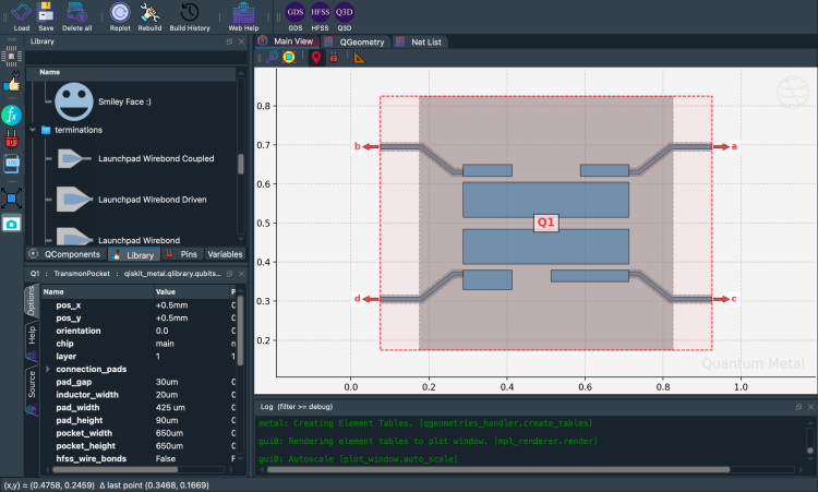
QPins — the dynamic way to connect components
A component designer can expose QPin endpoints. Pins let components link up: two transmons each expose a pin, a RouteMeander connects them into a CPW. Below, we recreate Q1 with named connection pads.
[28]:
from qiskit_metal.qlibrary.qubits.transmon_pocket import TransmonPocket

design.delete_all_components()

options = dict(
    pad_width="425 um",
    pocket_height="650um",
    connection_pads=dict(  # pin connectors
        a=dict(loc_W=+1, loc_H=+1),
        b=dict(loc_W=-1, loc_H=+1, pad_height="30um"),
        c=dict(loc_W=+1, loc_H=-1, pad_width="200um"),
        d=dict(loc_W=-1, loc_H=-1, pad_height="50um"),
    ),
)

q1 = TransmonPocket(
    design, "Q1", options=dict(pos_x="+0.5mm", pos_y="+0.5mm", **options)
)
[29]:
# Take a screenshot with the component highlighted and the pins shown
gui.rebuild()
gui.autoscale()
gui.edit_component("Q1")
gui.zoom_on_components(["Q1"])
gui.highlight_components(["Q1"])
gui.screenshot()
Access a pin by name:
[30]:
q1.pins.a
q1.pins["a"]
[30]:
{'points': [array([0.925, 0.7  ]), array([0.925, 0.69 ])],
 'middle': array([0.925, 0.695]),
 'normal': array([1., 0.]),
 'tangent': array([0., 1.]),
 'width': 0.01,
 'gap': 0.006,
 'chip': 'main',
 'parent_name': 2,
 'net_id': 0,
 'length': 0}
Editing component source from the API
gui.edit_component("Q1") opens the Qt source editor in the desktop GUI. In the headless viewer it’s a no-op — edit the source file directly and call gui.rebuild().
[31]:
gui.edit_component("Q1")
What’s next?
You’ve placed a transmon, modified it, compared variants, connected two qubits with a CPW, and inspected geometry. Plenty for one tutorial.
Want the concepts? 1.2 Bird’s eye view — what is a QDesign / QComponent / QRenderer, with diagrams.
Build the full chip: 1.3 Build a 4-qubit chip — ring layout, CPW routing, design variables.
Save & export: 1.4 Saving & exporting —
to_python_script()+ GDS for fabrication.Browse every component: QComponent Gallery — visual catalog of every qubit, coupler, route, resonator, and termination.
For more information, review the Introduction to Quantum Computing and Quantum Hardware lectures below
|
Lecture Video | Lecture Notes | Lab |
|
Lecture Video | Lecture Notes | Lab |
|
Lecture Video | Lecture Notes | Lab |
|
Lecture Video | Lecture Notes | Lab |
|
Lecture Video | Lecture Notes | Lab |
|
Lecture Video | Lecture Notes | Lab |