Note
This page was generated from tut/2-From-components-to-chip/2.22-Design-100-qubits-programmatically.ipynb.
2.22 Design 100 qubits programmatically
💡 Using this tutorial without the Qt GUI
This tutorial uses the desktop
MetalGUI. To follow along on Colab, Binder, JupyterHub, or any environment where Qt isn’t available, replace any ``gui.rebuild()`` / ``gui.screenshot()`` call with ``qm.view(design)`` — it renders the design to a matplotlibFigureyou can display inline or save withfig.savefig(...).See 1.1 Quick start for a complete runnable walkthrough and
`docs/headless-usage.rst<../../docs/headless-usage.rst>`__ for the full reference.
Prerequisite
For the LOM part of this tutorial, a working local installation of Ansys
N_x by N_y grid of qubits
A simple example of generating a large grid of qubits.
Using TransmonPocket and RouteMeander, we can generate a large, varied grid array of qubits. This is not a practical design given the lack of readouts or control lines to the qubits, just an example for how to make a design algorithmically.
[1]:
import qiskit_metal as metal
import qiskit_metal as qm
from qiskit_metal import designs
from qiskit_metal import Dict, Headings
[2]:
design = designs.DesignPlanar()
gui = qm.gui(design)
qm.view(design); gui.rebuild(), gui.screenshot(), gui.edit_component(...) work as in the desktop GUI.For the full desktop experience (Qt window, dockable panels):
pip install 'quantum-metal[gui]' and re-import.[3]:
from qiskit_metal.qlibrary.qubits.transmon_pocket import TransmonPocket
from qiskit_metal.qlibrary.tlines.meandered import RouteMeander
[4]:
design.overwrite_enabled = True
Design
We can vary how big we want the grid to be by changing N_x/N_y (number of qubits along the x/y axis). Be careful as very large arrays can take a fair bit of time to generate. We modify the chip size so it contains all of the qubits.
[5]:
N_x = 10
N_y = 10
[6]:
design.delete_all_components()

design.chips.main.size.size_x = str((N_x + 1) * 3) + "mm"
design.chips.main.size.size_y = str((N_y + 1) * 3) + "mm"

design.chips.main.size.center_x = str((N_x - 1) * 1.5) + "mm"
design.chips.main.size.center_y = str((N_y - 0.5) * 1.5) + "mm"
First we generate the qubits. We use some simple math to generate the offset pattern in order to make the bus resonators easier to connect.
[7]:
# Loop to generate and draw the qubits
for x in range(N_x):
for y in range(N_y):
options = dict(
pos_x=str(x * 3000) + "um",
pos_y=str(y * 3000 + (x % 2) * 1500) + "um",
orientation="-90",
connection_pads=dict(
B0=dict(loc_W=-1, loc_H=-1, pad_width="75um"),
B1=dict(loc_W=-1, loc_H=+1, pad_width="120um"),
B2=dict(loc_W=+1, loc_H=-1, pad_width="120um"),
B3=dict(loc_w=+1, loc_H=+1, pad_width="90um"),
),
)
obj = TransmonPocket(design, "Q_" + str(x) + "_" + str(y), options)
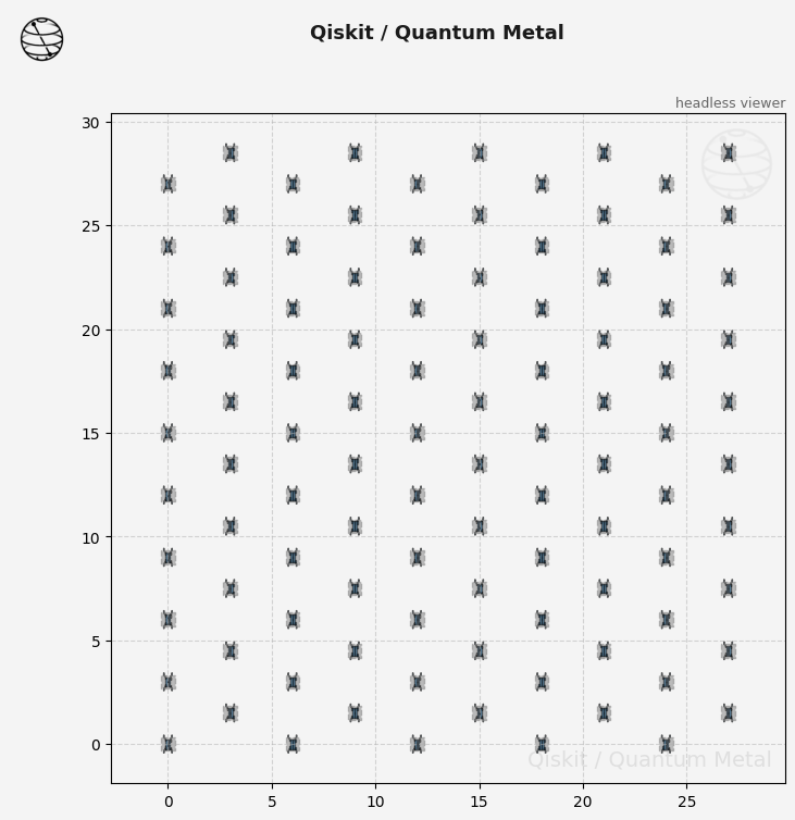
gui.rebuild()
gui.autoscale()
[7]:

[8]:
gui.screenshot()
Next, we generate the route meanders. As we used consistent naming schemes for the qubits and pins, we can loop through them with out issue. We also have the length vary based on which qubit is being connected, such that no qubit should be connected to two resonators of the same frequency.
[9]:
for x in range(N_x):
    for y in range(N_y):
        # "upward" connection, avoids drawing connectors for 'top' row. Changes connector length by +/-50um to avoid frequency collisions
        if y < (N_y - 1):
            connectorAD = RouteMeander(
                design,
                "CU_" + str(x) + "_" + str(y),
                options=dict(
                    total_length=str(7 + (y % 2) * 0.5) + "mm",
                    fillet="99um",
                    lead=dict(start_straight="0.5mm", end_straight="0.25mm"),
                    meander=dict(asymmetry="-700um"),
                    pin_inputs=dict(
                        start_pin=dict(
                            component="Q_" + str(x) + "_" + str(y), pin="B0"
                        ),
                        end_pin=dict(
                            component="Q_" + str(x) + "_" + str(y + 1), pin="B3"
                        ),
                    ),
                ),
            )

        # "sideways" connection, avoids drawing for far right col, and for top qubit in odd col. Changes connector length by +/- 25um
        # to avoid frequency collisions
        if x < (N_x - 1) and (not (x % 2 and y == (N_y - 1))):
            connectorBC = RouteMeander(
                design,
                "CS_" + str(x) + "_" + str(y),
                options=dict(
                    total_length=str(6 + (y % 2) * 0.5) + "mm",
                    fillet="99um",
                    lead=Dict(start_straight="0.3mm", end_straight="0.25mm"),
                    meander=Dict(asymmetry="-200um"),
                    pin_inputs=Dict(
                        start_pin=Dict(
                            component="Q_" + str(x) + "_" + str(y), pin="B1"
                        ),
                        end_pin=Dict(
                            component="Q_" + str(x + 1) + "_" + str(y + (x % 2)),
                            pin="B2",
                        ),
                    ),
                ),
            )


gui.rebuild()
gui.autoscale()
[9]:
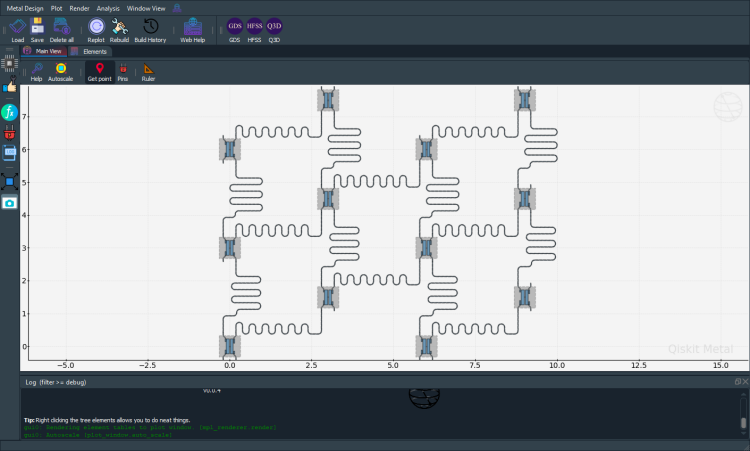
[10]:
gui.screenshot()

100 qubits in a 10x10 grid with bus couplers
Analysis
We can quickly check if we have designed the qubits well with an LOM analysis. First we select the design that we want to analyse and the tool to use for any simulation.
[11]:
from qiskit_metal.analyses.quantization import LOManalysis

c1 = LOManalysis(design, "q3d")
You can review and update the Analysis default setup following the examples in the next two cells.
[12]:
c1.sim.setup
[12]:
{'name': 'Setup',
 'reuse_selected_design': True,
 'reuse_setup': True,
 'freq_ghz': 5.0,
 'save_fields': False,
 'enabled': True,
 'max_passes': 15,
 'min_passes': 2,
 'min_converged_passes': 2,
 'percent_error': 0.5,
 'percent_refinement': 30,
 'auto_increase_solution_order': True,
 'solution_order': 'High',
 'solver_type': 'Iterative'}
Let’s change the name of the setup and increase the maximum number of passes.
[13]:
c1.sim.setup.name = "LOM"
c1.sim.setup.max_passes = 14

# To change multiple settings use the following method:
# c1.sim.setup_update(name = 'LOM', max_passes = 14)

c1.sim.setup
[13]:
{'name': 'LOM',
 'reuse_selected_design': True,
 'reuse_setup': True,
 'freq_ghz': 5.0,
 'save_fields': False,
 'enabled': True,
 'max_passes': 14,
 'min_passes': 2,
 'min_converged_passes': 2,
 'percent_error': 0.5,
 'percent_refinement': 30,
 'auto_increase_solution_order': True,
 'solution_order': 'High',
 'solver_type': 'Iterative'}
For our analysis we will pick the first qubit, Q_0_0, making sure to apply open terminations to the connection pads. The default bounding box is sufficient for a simple analysis. By passing the parameter components to the sim.run() method, the design is rendered automatically. Not passing it skips the rendering and tries to run the analysis on the latest design. If a design is not found, the full metal design is rendered.
[14]:
c1.sim.run(
    components=["Q_0_0"],
    open_terminations=[
        ("Q_0_0", "B0"),
        ("Q_0_0", "B1"),
        ("Q_0_0", "B2"),
        ("Q_0_0", "B3"),
    ],
)
---------------------------------------------------------------------------
RuntimeError                              Traceback (most recent call last)
Cell In[14], line 1
----> 1 c1.sim.run(
      2     components=["Q_0_0"],
      3     open_terminations=[
      4         ("Q_0_0", "B0"),
      5         ("Q_0_0", "B1"),
      6         ("Q_0_0", "B2"),
      7         ("Q_0_0", "B3"),
      8     ],
      9 )

File ~/CODE_REPOS/quantum_hardware/qiskit-metal/src/qiskit_metal/analyses/core/simulation.py:205, in QSimulation.run(self, *args, **kwargs)
    201 def run(self, *args, **kwargs):
    202     """Alias for run_sim() necessary to implement super-class method, while
    203     preventing method name collision when sim and non-sim QAnalysis classes are inherited.
    204     """
--> 205     self.run_sim(*args, **kwargs)

File ~/CODE_REPOS/quantum_hardware/qiskit-metal/src/qiskit_metal/analyses/simulation/lumped_elements.py:138, in LumpedElementsSim.run_sim(self, name, components, open_terminations, box_plus_buffer)
    135 self.clear_data()
    137 if not self.renderer_initialized:
--> 138     self._initialize_renderer()
    140 renderer_design_name = self._render(
    141     name=name,
    142     solution_type="capacitive",
   (...)    146     vars_to_initialize=Dict(),
    147 )
    149 self._analyze()

File ~/CODE_REPOS/quantum_hardware/qiskit-metal/src/qiskit_metal/analyses/core/simulation.py:146, in QSimulation._initialize_renderer(self)
    144 def _initialize_renderer(self):
    145     """Starts the renderer by executing the routine of the selected renderer."""
--> 146     self.renderer.start()

File ~/CODE_REPOS/quantum_hardware/qiskit-metal/src/qiskit_metal/renderers/renderer_base/renderer_base.py:382, in QRenderer.start(self, force)
    377         self._close_renderer()
    379 # TODO: move the code line below to inside the `if force or not initiated`,
    380 #  but only after the TODO before the `if` is completed
    381 # try to initialize the renderer
--> 382 self.initiated = self._initiate_renderer()
    384 return self.initiated

File ~/CODE_REPOS/quantum_hardware/qiskit-metal/src/qiskit_metal/renderers/renderer_ansys/ansys_renderer.py:343, in QAnsysRenderer._initiate_renderer(self)
    341     self.rapp = HfssApp()
    342 except NameError:
--> 343     raise RuntimeError(
    344         "\n\nCannot connect to Ansys HFSS — win32com (Windows COM) is not available.\n\n"
    345         "This renderer requires:\n"
    346         "  1. Microsoft Windows  (COM automation is Windows-only)\n"
    347         "  2. Ansys Electronics Desktop (HFSS) installed and licensed\n"
    348         "  3. pywin32 installed:  pip install pywin32\n\n"
    349         "Running on macOS or Linux? Use one of these alternatives instead:\n"
    350         "  • ElmerFEM open-source FEM:  see tutorial 4.19 (tutorials/4-Analysis/)\n"
    351         "  • Export to GDS and simulate externally:  see tutorial 3.2\n"
    352         "  • pyaedt-based renderer (Windows + Ansys 2022+):  QAnsysPyaedtRenderer\n"
    353     ) from None
    354 self.rdesktop = self.rapp.get_app_desktop()
    355 if self.rdesktop.project_count() == 0:

RuntimeError:

Cannot connect to Ansys HFSS — win32com (Windows COM) is not available.

This renderer requires:
  1. Microsoft Windows  (COM automation is Windows-only)
  2. Ansys Electronics Desktop (HFSS) installed and licensed
  3. pywin32 installed:  pip install pywin32

Running on macOS or Linux? Use one of these alternatives instead:
  • ElmerFEM open-source FEM:  see tutorial 4.19 (tutorials/4-Analysis/)
  • Export to GDS and simulate externally:  see tutorial 3.2
  • pyaedt-based renderer (Windows + Ansys 2022+):  QAnsysPyaedtRenderer
We then use the results of that simulation to complete a LOM analysis. The input values should be modified based on the simulation passes and the set frequencies of the resonators.
[15]:
c1.setup.junctions = Dict({"Lj": 12.31, "Cj": 2})
c1.setup.freq_readout = 6.6
c1.setup.freq_bus = [6.0, 6.2, 6.4]

c1.run_lom()
07:22PM 55s WARNING [run_lom]: Please initialize the capacitance_matrix before executing this method.`self.sim.capacitance_matrix = pd.DataFrame(...)`
Once you are done with your analysis, please close it with close(). This will free up resources currently occupied by qiskit-metal to communiate with the tool.
[16]:
c1.sim.close()
GDS Render
[17]:
chip_gds = design.renderers.gds
[18]:
chip_gds.options["no_cheese"]["buffer"] = "50um"
chip_gds.options["path_filename"] = "../../resources/Fake_Junctions.GDS"
[19]:
chip_gds.export_to_gds("NxN_Chip.gds")
07:22PM 59s WARNING [import_junction_gds_file]: Not able to find file:"../../resources/Fake_Junctions.GDS". Not used to replace junction. Checked directory:"/Users/zlatkominev/CODE_REPOS/quantum_hardware/qiskit-metal/docs/resources".
[19]:
1
We can close the GUI now that we have finished the design.
[20]:
gui.main_window.close()
For more information, review the Introduction to Quantum Computing and Quantum Hardware lectures below
|
Lecture Video | Lecture Notes | Lab |
|
Lecture Video | Lecture Notes | Lab |
|
Lecture Video | Lecture Notes | Lab |
|
Lecture Video | Lecture Notes | Lab |
|
Lecture Video | Lecture Notes | Lab |
|
Lecture Video | Lecture Notes | Lab |