SNAIL
- class SNAIL(design: QDesign, name: str | None = None, options: Dict | None = None, make: bool = True, component_template: Dict | None = None)[source]
A SNAIL (Superconducting Nonlinear Asymmetric Inductive eLement).
Inherits the “QComponent” class.
A SNAIL is a superconducting loop interrupted by
nlarge Josephson junctions on one arm (heren = 3) and a single smaller junction (Josephson energyalpha * E_J) on the opposite arm. The asymmetry between the two arms gives the element a tunable third-order (three-wave mixing) nonlinearity that a symmetric two-junction SQUID does not have, which makes it the building block of SNAIL parametric amplifiers (SPAs) and Kerr-free three-wave mixers.Physics
With
phithe superconducting phase across the small junction andphi_ext = 2*pi*Phi_ext/Phi_0the reduced external flux, the SNAIL potential is (Frattini 2017):U(phi)/E_J = - alpha*cos(phi) - n*cos((phi_ext - phi)/n)
Taylor-expanding about its minimum
phi_mingivesU_eff/E_J = c2*p^2 + c3*p^3 + c4*p^4 + ...(p = phi - phi_min), where the coefficientsc2, c3, c4are set purely by(n, alpha, Phi_ext).c2is the (flux-tunable) linear inductance,c3the three-wave-mixing strength andc4the Kerr. The useful operating point is the Kerr-free flux wherec4 -> 0whilec3stays large: pure three-wave mixing with no self-Kerr / Stark shift, which is what preserves gain and quantum efficiency at strong pump drive.n = 3is the smallest array that simultaneously (a) admits analphabelow the single-well bound while still giving useful inductive tunability, and (b) opens a region in(alpha, Phi_ext)wherec4crosses zero withc3still large. Limiting cases:n = 1is a SQUID (pure cosine,c3 = 0, no three-wave mixing);n >> 1approaches the linear RF-SQUID / fluxonium regime.Single-well design constraint: keep
alpha < 1/n(i.e.alpha < 1/3forn = 3). Above this the potential develops multiple inequivalent minima and becomes hysteretic (flux-qubit-like), which is unusable for clean three-wave mixing. The fabricated devices below sit just under the bound atalpha ~ 0.29. (More precisely the non-hysteretic region is a 2-D area in the(alpha, Phi_ext)plane;alpha < 1/nis the canonical rule of thumb, not an all-flux guarantee.)References
Frattini et al., “3-wave mixing Josephson dipole element”, Appl. Phys. Lett. 110, 222603 (2017), arXiv:1702.00869 – introduces the SNAIL; source of
n = 3,alpha = 0.29,Phi_ext = 0.41 Phi_0,I0 = 7.1 / 2.0 uA.Frattini et al., “Optimizing the Nonlinearity and Dissipation of a SNAIL Parametric Amplifier for Dynamic Range”, Phys. Rev. Applied 10, 054020 (2018), arXiv:1806.06093 – arraying (
M = 1, 10, 20) to raise saturation power; also usesalpha = 0.09.Sivak et al., “Kerr-free three-wave mixing in superconducting quantum circuits”, Phys. Rev. Applied 11, 054060 (2019), arXiv:1902.10575 – Kerr-free operation,
M = 20array, resonator tunable 6.2-7.2 GHz.Miano et al., “Frequency-tunable Kerr-free three-wave mixing with a gradiometric SNAIL”, Appl. Phys. Lett. 120, 184002 (2022), arXiv:2112.09785 – restates the
alpha < 1/3bound; two-loop gradiometric variant (not drawn here).Josephson inductance relation:
L_J = Phi_0/(2*pi*I0) = hbar/(2*e*I0)(Phi_0 = h/2e);I0 = 1 uA -> L_J = 329 pH.
Typical device parameters (measured values are from Frattini 2017 and recur in Frattini 2018 / Sivak 2019; inductances are computed from the critical currents). Useful when choosing junction inductances for a renderer/analysis:
n = 3large junctions, eachI0 ~ 7.1 uA->L_J ~ 46 pH(theLjdefault).one small junction,
I0 ~ 2.0 uA->L_J ~ 165 pH(theLj_smalldefault), i.e.L_J,small = L_J,large / alphawithalpha = I0_small / I0_large ~ 0.29.Kerr-free point near
alpha ~ 0.29,Phi_ext ~ 0.41 * Phi_0; reported flux bias points cluster inPhi_ext/Phi_0 ~ 0.33-0.45.the three nominally-identical large junctions are made from two Dolan bridges (Al-on-Si); SNAILs are typically arrayed in series (
M = 10-20) to raise saturation power – this class draws one.NOTE: the source papers specify the element electrically (critical currents,
alpha, flux) and do not tabulate on-chip junction overlap areas or loop dimensions, so the layout dimensions below are schematic (SQUID_LOOP-scale), not lifted from a published mask. Only the electrical parameters are grounded.
Junction representation in Quantum Metal
A Josephson junction has two distinct representations in this library, and this component deliberately uses only the first:
Schematic / analysis – a 2-point
LineStringin thejunctionqgeometry table with awidth. The Ansys/HFSS and pyEPR renderers turn each such row into a lumped Josephson inductance (hfss_inductance). This is whatTransmonPocketdoes and what makes the element EM-/EPR-analyzable. It is a meshing placeholder, not the physical junction.Physical / fabrication – the real sub-micron junction geometry (overlapping fingers/pads on a separate e-beam layer), drawn by the dedicated p-cells
jj_dolan(Dolan, Appl. Phys. Lett. 31, 337, 1977) andjj_manhattan(Pop et al., Nature 508, 369, 2014). Those carry the realum-scale dimensions for the GDS mask and, per their own docstrings, must not be rendered for EM simulation.
SNAILemits the four junctions as the schematic LineStrings (three large sharingLj, one small withLj_small) – the analysis path. For a fabrication-faithful mask, overlay ajj_dolan/jj_manhattanp-cell at each junction location on the e-beam layer and exclude the schematic junctions from the GDS export. Keeping the two representations in separate components is intentional: the physical junction has features that break EM meshing, while the lumped line is exactly what the simulator wants.alphais ultimately set by the physical junction overlap areas / critical currents at fabrication; here the asymmetry is expressed for analysis throughLjvsLj_smalland marked geometrically by the narrower defaultsegment_lower_widthon the small-junction (lower) arm.Geometry
Follows the same rectangular-loop convention as
SQUID_LOOP, built from rectangles: a left plate (plate1), the upper arm (seg a/seg ab/seg bseparated by threeJJ_gapbreaks where the three large junctions sit), the lower arm (seg a lower/seg b lowerseparated by a singleJJ_gap_smallbreak where the small junction sits), a vertical connector (seg c), a horizontal lead (seg d) and a right plate (plate2). The lower arm is automatically padded so that both arms close onto the same vertical connector, keeping the loop rectangular for any junction spacing.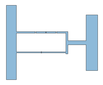
- Default Options:
plate1_width: ‘5.5um’ – width of plate1 (left)
plate1_height: ‘40um’ – height of plate1 (left)
plate1_pos_x: ‘0’ – origin of plate1 (left) in x
plate1_pos_y: ‘0’ – origin of plate1 (left) in y
squid_gap: ‘10um’ – vertical space between the upper and lower arms
segment_a_length: ‘10um’ – length of seg a (first upper-arm segment)
segment_a_width: ‘1um’ – width of the upper-arm segments
JJ_gap: ‘0.5um’ – break for each of the three large junctions (upper arm)
segment_ab_length: ‘5um’ – length of the islands between the large junctions
segment_b_length: ‘5um’ – length of seg b (last upper-arm segment)
segment_b_width: ‘1um’ – width of seg b
JJ_gap_small: ‘0.3um’ – break for the single small junction (lower arm)
segment_lower_width: ‘0.6um’ – width of the lower (small-junction) arm
segment_c_width: ‘1um’ – width of the vertical connector seg c
segment_d_length: ‘10um’ – length of seg d
segment_d_width: ‘2um’ – width of seg d
plate2_width: ‘6um’ – width of plate 2 (right)
plate2_height: ‘30um’ – height of plate 2 (right)
Lj: ‘0.046nH’ – Josephson inductance of each large junction (~46 pH, from I0 ~ 7.1 uA in Frattini et al. 2017); written to the
junctionqgeometry table for HFSS/pyEPRLj_small: ‘0.165nH’ – Josephson inductance of the small junction (~165 pH, from I0 ~ 2.0 uA; equals Lj / alpha with alpha ~ 0.29)
inductor_width: ‘1um’ – width of the rendered junction strips (for HFSS/other EM software meshing; not the physical junction size)
pin_width: ‘5um’ – width of the connection pins on plate1/plate2
Pins:
a(left, on plate1) andb(right, on plate2) so the SNAIL can be wired into a larger design with a route. The four junctions are emitted to thejunctionqgeometry table (three large withLj, one small withLj_small) so the element is HFSS-eigenmode / pyEPR analyzable; keepCj = Rj = 0(the renderer default) for pyEPR.Create a new Metal component and adds it’s default_options to the design.
- param design:
The parent design.
- type design:
QDesign
- param name:
Name of the component. Auto-named if possible.
- type name:
str
- param options:
User options that will override the defaults. Defaults to None.
- type options:
dict
- param make:
True if the make function should be called at the end of the init. Options be used in the make function to create the geometry. Defaults to True.
- type make:
bool
- param component_template:
User can overwrite the template options for the component that will be stored in the design, in design.template, and used every time a new component is instantiated. Defaults to None.
- type component_template:
dict
- raises ValueError:
User supplied design isn’t a QDesign
- Note: Information copied from QDesign class.
self._design.overwrite_enabled (bool): When True - If the string name, used for component, already exists in the design, the existing component will be deleted from design, and new component will be generated with the same name and newly generated component_id, and then added to design.
When False - If the string name, used for component, already exists in the design, the existing component will be kept in the design, and current component will not be generated, nor will be added to the design. The variable design.self.status will still be NotBuilt, as opposed to Initialization Successful.
Either True or False - If string name, used for component, is NOT being used in the design, a component will be generated and added to design using the name.
Attributes
- TOOLTIP = 'QComponent'
- class_name
the full module name with the class name. e.g., qiskit_metal.qlibrary.qubits.TransmonPocket.
- Returns:
Class name
- Return type:
- Type:
Return the full name of the class
- component_metadata = {'_qgeometry_table_junction': 'True', '_qgeometry_table_poly': 'True', 'short_name': 'component'}
Component metadata
- default_options = {'JJ_gap': '0.5um', 'JJ_gap_small': '0.3um', 'Lj': '0.046nH', 'Lj_small': '0.165nH', 'inductor_width': '1um', 'pin_width': '5um', 'plate1_height': '40um', 'plate1_pos_x': '0', 'plate1_pos_y': '0', 'plate1_width': '5.5um', 'plate2_height': '30um', 'plate2_width': '6um', 'segment_a_length': '10um', 'segment_a_width': '1um', 'segment_ab_length': '5um', 'segment_b_length': '5um', 'segment_b_width': '1um', 'segment_c_width': '1um', 'segment_d_length': '10um', 'segment_d_width': '2um', 'segment_lower_width': '0.6um', 'squid_gap': '10um'}
Default drawing options
- logger
The Qiskit Metal Logger.
- Returns:
Logger
- Return type:
- name
Name of the component.
- options = {}
A dictionary of the component-designer-defined options. These options are used in the make function to create the QGeometry and QPins. All options should have string keys and preferrable string values.
- qgeometry_types
Get a list of the names of the element tables.
- Returns:
Name of element table or type; e.g., ‘poly’ and ‘path’
- Return type:
List[str]
- pins
Dictionary of pins. Populated by component designer in make function using add_pin.
- metadata
Metadata allows a designer to store extra information or analysis results.
- status
Stores the latest status of the component. Values include:
Initialization Successful,Build Failed, etc.
Methods
- add_dependency(parent: str, child: str)
Add a dependency between one component and another. Calls parent design.
- add_pin(name: str, points: ndarray, width: float, input_as_norm: bool = False, chip: str | None = None, gap: float | None = None) None
Adds a pin from two points which are normal/tangent to the intended plane of the pin. The normal should ‘point’ in the direction of intended connection. Adds the new pin as a subdictionary to parent component’s pins dictionary.
- Parameters:
name (*) – name of the pin
points (*) – [[x1,y1],[x2,y2]] for the normal/tangent line
width (*) – the width of the intended connection (eg. qubit bus pad arm)
input_as_norm (*) – Indicates if the points are tangent or normal to the pin plane. Defaults to False.. Make True for normal.
parent (*) – The id of the parent component.
chip (*) – the name of the chip the pin is located on. Defaults to None, which is
self.options.chip. (converted to)
gap (*) – the dielectric gap of the pin for the purpose of representing as a port for simulations. Defaults to None which is converted to 0.6 * width.
- Dictionary containing pins information:
points (numpy.ndarray) - two (x,y) points which represent the edge of the pin for another component to attach to (eg. the edge of a CPW TL)
middle (numpy.ndarray) - an (x,y) which represents the middle of the points above, where the pin is represented.
normal (numpy.ndarray) - the normal vector of the pin, pointing in direction of intended connection
tangent (numpy.ndarray) - 90 degree rotation of normal vector
width (float) - the width of the pin
chip (str) - the chip the pin is on
parent_name - the id of the parent component
net_id - net_id of the pin if connected to another pin. Defaults to 0, indicates not connected))
* = pin
. = outline of component
—> = the list being passed in as ‘points’ [[x1,y1],[x2,y2]]
normal vector
..........
         .
--------->*
         .
..........
tangent vector
..........^
         .|
         .*
         .|
..........|
- add_qgeometry(kind: str, geometry: dict, subtract: bool = False, helper: bool = False, layer: int | str | None = None, chip: str | None = None, **kwargs) None
Add QGeometry.
Takes any additional options in options.
- Parameters:
kind (str) – The kind of QGeometry, such as ‘path’, ‘poly’, etc. All geometry in the dictionary should have the same kind, such as Polygon or LineString.
geometry (Dict[BaseGeometry]) – Key-value pairs of name of the geometry you want to add and the value should be a shapely geometry object, such as a Polygon or a LineString.
subtract (bool) – Subtract from the layer. Defaults to False.
helper (bool) – Is this a helper object. If true, subtract must be false Defaults to False.
layer (int, str) – The layer to which the set of QGeometry will belong Defaults to None, which is converted to self.options.chip.
chip (str) – Chip name. Defaults to None, which is converted to
self.options.chip.
kwargs (dict) – Parameters dictionary
- Assumptions:
Assumes all geometry in the geometry argument are homogeneous in kind; i.e., all lines or polys etc.
- connect_components_already_in_design(pin_name_self: str, comp2_id: int, pin2_name: str) int
- WARNING: Do NOT use this method during generation of component instance.
This method is expecting self to be added to design._components dict. More importantly, the unique id of self component needs to be in design._components dict.
- classmethod get_template_options(design: QDesign, component_template: Dict | None = None, logger_: Logger | None = None, template_key: str | None = None) Dict
Creates template options for the Metal Component class required for the class to function, based on the design template; i.e., be created, made, and rendered. Provides the blank option structure required.
The options can be extended by plugins, such as renderers.
- Parameters:
design (QDesign) – Design class. Should be the class, not the instance.
component_template (Dict) – Template options to overwrite the class ones (default: None)
logger (logging.Logger) – A logger for errors. Defaults to None.
template_key (str) – The template key identifier. If None, then uses cls._get_unique_class_name(). Defaults to None.
- Returns:
dictionary of default options based on design template.
- Return type:
Dict
- parse_options(options: Dict | None = None) Dict
Parse the options, converting string into interpreted values. Parses units, variables, strings, lists, and dictionaries. Explained by example below.
- Parameters:
options (dict) – If left None, then self.options is used. Defaults to None.
- Returns:
Parsed value
- Return type:
Calls self.design.parse_options.
See self.parse_value for more information.
- parse_value(value: Any | List | Dict | Iterable) Any | List | Dict | Iterable
Parse a string, mappable (dict, Dict), iterable (list, tuple) to account for units conversion, some basic arithmetic, and design variables. This is the main parsing function of Qiskit Metal.
- Parameters:
- Returns:
Parse value
- Return type:
- Handled Inputs:
- Strings:
- Strings of numbers, numbers with units; e.g., ‘1’, ‘1nm’, ‘1 um’
Converts to int or float. Some basic arithmetic is possible, see below.
- Strings of variables ‘variable1’.
Variable interpretation will use string method isidentifier ‘variable1’.isidentifier()`
- Dictionaries:
Returns ordered Dict with same key-value mappings, where the values have been subjected to parse_value.
- Itterables(list, tuple, …):
Returns same kind and calls itself parse_value on each element.
- Numbers:
Returns the number as is. Int to int, etc.
- Arithmetic:
Some basic arithmetic can be handled as well, such as ‘-2 * 1e5 nm’ will yield float(-0.2) when the default units are set to mm.
- Default units:
User units can be set in the design. The design will set config.DEFAULT.units
Examples
- See the docstring for this module.
>> ?qiskit_metal.toolbox_metal.parsing
- populate_to_track_table_usage() None
Use the element_handler to get a list of all the table names used in QGeometry.
The dict qgeometry_able_usage should get updated by add_qgeometry(). This dict is used to get a summary tables used for this component.
- qgeometry_bounds() Tuple
Fetched the component bound dict_value.
- Returns:
containing (minx, miny, maxx, maxy) bound values for the bounds of the component as a whole.
- Return type:
- Uses:
design.qgeometry.get_component_bounds
- qgeometry_dict(element_type: str) Dict[str, BaseGeometry]
Returns a dict of element qgeometry (shapely geometry) of the component as a python dict, where the dict keys are the names of the qgeometry and the corresponding values are the shapely geometries.
- Parameters:
element_type (str) – Name of element table or type; e.g., ‘poly’ and ‘path’
- Returns:
Geometry diction or None if an error in the name of the element type (ie. table)
- Return type:
List[BaseGeometry]
- qgeometry_list(element_type: str = 'all') List[BaseGeometry]
Returns a list of element qgeometry (shapely geometry) of the component as a python list of shapely geometries.
- Parameters:
element_type (str) – Name of element table or type; e.g., ‘poly’ and ‘path’. Can also specify all
- Returns:
Geometry list or None if an error in the name of the element type (ie. table)
- Return type:
List[BaseGeometry]
- qgeometry_plot(ax: matplotlib.axes.Axes = None, plot_kw: dict | None = None) List
Draw all the qgeometry of the component (polys and path etc.)
- Parameters:
ax (matplotlib.axes.Axes) – Matplotlib axis to draw on. Defaults to None. When None, it gets the current axis.
plot_kw (dict) – Parameters dictionary.
- Returns:
The list of qgeometry draw
- Return type:
List
- Example use:
Suppose you had a component called q1:
fig, ax = draw.mpl.figure_spawn() q1.qgeometry_plot(ax)
- qgeometry_table(element_type: str) DataFrame
Returns the entire element table for the component.
- Parameters:
element_type (str) – Name of element table or type; e.g., ‘poly’ and ‘path’
- Returns:
Element table for the component or None if an error in the name of the element type (ie. table)
- Return type:
pd.DataFrame
- rebuild() None
Builds the QComponent.
This is the main action function of a QComponent, call it qc. It converts the qc.options into QGeometry with all of the required options, such as the geometry points, layer number, materials, etc. needed to render.
The build clears the existing QGeometry and QPins and then calls the qc.make function, which is written by the component developer to implement the logic (using the metal. draw module) to convert the qc.options into the QGeometry.
Build status: The function also sets the build status of the component. It sets to failed when the component is created, and then it sets to good when it is done with no errors. The user can also set other statuses, which can appear if the code fails to reach the final line of the build, where the build status is set to good.
- Raises:
Exception – Component build failure
- to_script(thin: bool = False, is_part_of_chip: bool = False) Tuple
- Parameters:
thin – If true then any key in the QComponent’s options whose value is the same value as the default will not be included in the body
is_part_of_chip – If true, body will not include header code
Returns: Code that if copy-pasted into a .py file would generate an instance of this class with the same properties as the instance calling this function